Visible to Intel only — GUID: hdd1485800790583
Ixiasoft
1.7.1. Stratix® 10 Device Recommendations
1.7.2. Stratix® V Device Recommendations
1.7.3. Stratix IV Device Recommendations
1.7.4. Arria® 10 Device Recommendations
1.7.5. Arria® V Device Recommendations
1.7.6. Arria II Device Recommendations
1.7.7. Cyclone® 10 Device Recommendations
1.7.8. Cyclone® V Device Recommendations
1.7.9. Cyclone® IV Device Recommendations
1.7.10. Cyclone III Device Recommendations
Visible to Intel only — GUID: hdd1485800790583
Ixiasoft
1.2.1.2. Loss Tangent
Loss tangent (tan(δ)) is a measure of signal loss as the signal propagates down the transmission line. Material datasheets and PCB manufacturers commonly refer to this signal loss as the dissipation factor (Df). tan(δ) or Df is the result of electromagnetic wave absorption by the dielectric material and depends on the material’s structure and glass-resin composition. A lower loss tangent results in more of the original transmitted signal getting through to its destination. This is important for transceiver-based designs where multi-gigabit signals must be transmitted across long backplane channels. A large loss tangent means more dielectric absorption and less of the transmitted signal is getting through to its destination. Below equation shows the signal attenuation due to the loss tangent, measured in decibels per inch (dB/in).
Where:
- is the frequency in GHz
- tan(δ) is the dimensionless loss tangent
- εr is the relative dielectric constant of the material
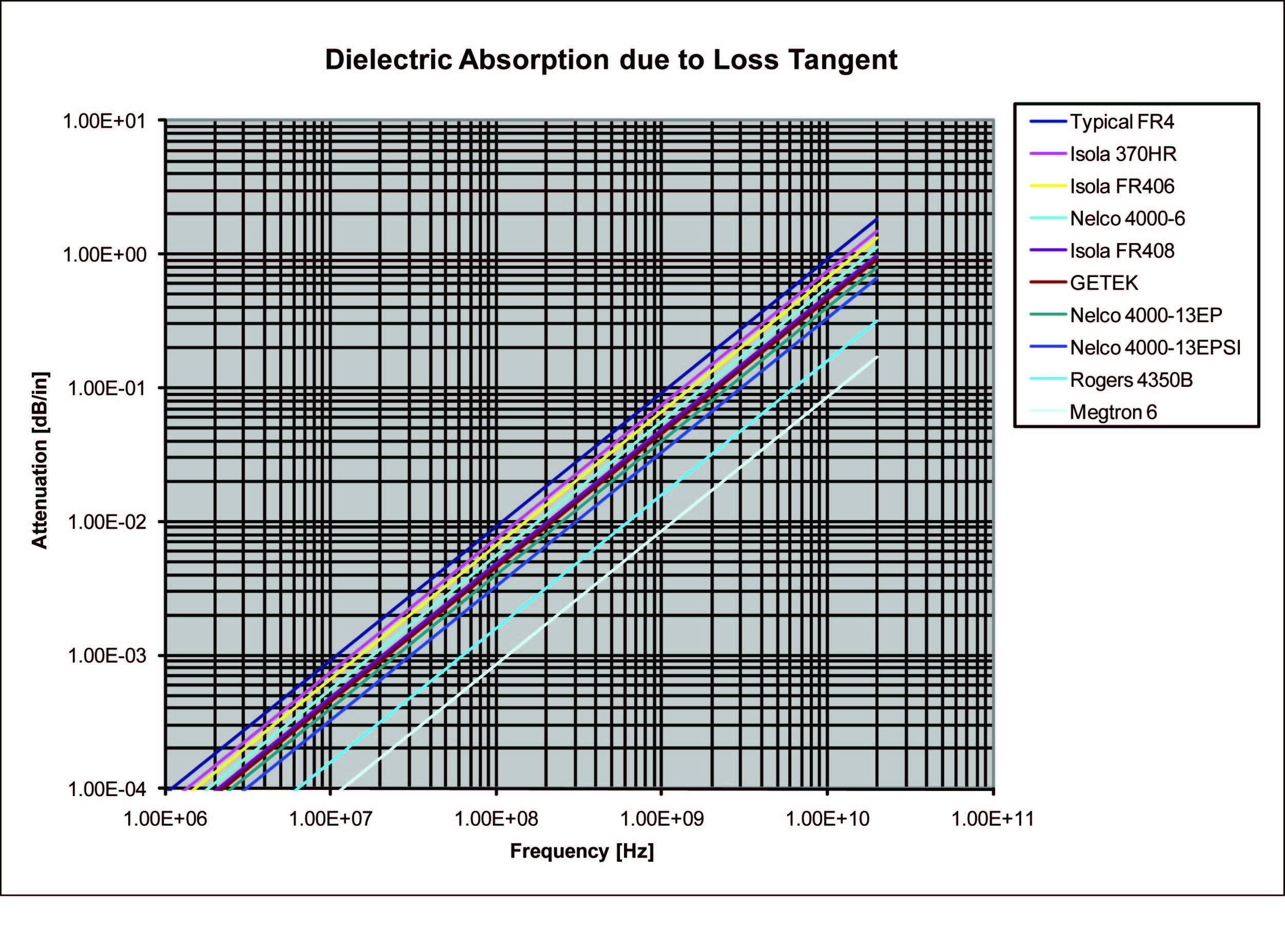
Ideally, selecting the lowest loss material is the best choice. However, lower loss comes at an increased cost tradeoff. A better approach is to plot attenuation equation against frequency for the various material choices under consideration and compare the signal attenuation for the target data rate and reach required. For example, below figure shows this attenuation for some common PCB materials by plotting attenuation equation against frequency up to 20 GHz.
Figure 2. Comparison of Loss Tangent Attenuation
| Material | εr | tan(δ) |
|---|---|---|
| Typical FR4 | 4 | 0.02 |
| GETEK | 3.9 | 0.01 |
| Isola 370HR | 4.17 | 0.016 |
| Isola FR406 | 4.29 | 0.014 |
| Isola FR408 | 3.70 | 0.011 |
| Panasonic Megtron 6 | 3.4 | 0.002 |
| Nelco 4000-6 | 4.12 | 0.012 |
| Nelco 4000-13 EP | 3.7 | 0.009 |
| Nelco 4000-13 EP SI | 3.2 | 0.008 |
| Rogers 4350B | 3.48 | 0.0037 |
For example, suppose a design running at 10 Gbps requiring a maximum reach of 40 inches is targeted for the Nelco 4000-13 EP material. Because the Nyquist frequency is 5 GHz for a 10 Gbps data rate, the resulting loss that is due solely to the dielectric absorption of Nelco 4000-13EP material is 0.2 dB per inch multiplied by 40 inches of trace length, resulting in 8 dB of signal attenuation just from the material dielectric absorption. Next, suppose a maximum total loss budget of 10 dB is required for a signal to be properly recovered at the receiver. In this case, most of the signal loss is already consumed by the material dielectric, so a lower loss material or shorter reach must be considered, because additional conductor losses are expected from trace discontinuities, skin effect, vias, and connector assemblies that may be present in the transmission path.
Furthermore, as an example of material cost considerations, below table lists an approximate normalized cost factor relationship for some common PCB materials relative to FR4. Because material costs can vary depending on the PCB vendor, consult the PCB vendor for their latest pricing and relative cost factor data when deciding on material performance versus cost tradeoffs.
| Material Group | Vendor Specific | FR4 Relative Cost Factor |
|---|---|---|
| 170 Tg FR4 (Baseline) | Nelco 4000-6 | 1 |
| High Tg / Reliability-Filled | Isola 370HR | 1.1 |
| High Speed / Low Loss | Isola FR408 | 1.8 |
| High Speed / Low Loss | Nelco 4000-13 EP | 2.1 |
| High Speed / Very Low Loss | Nelco 4000-13 EP SI | 3.2 |
| High Frequency | Arlon 85N | 4 |
| High Frequency | IS680-3.45 | 4.2 |
| High Speed / Very Low Loss | Panasonic Megtron 6 | 5 |
| High Frequency | Rogers 4350B | 5.6 |