Visible to Intel only — GUID: nlc1485884882853
Ixiasoft
1.7.1. Stratix® 10 Device Recommendations
1.7.2. Stratix® V Device Recommendations
1.7.3. Stratix IV Device Recommendations
1.7.4. Arria® 10 Device Recommendations
1.7.5. Arria® V Device Recommendations
1.7.6. Arria II Device Recommendations
1.7.7. Cyclone® 10 Device Recommendations
1.7.8. Cyclone® V Device Recommendations
1.7.9. Cyclone® IV Device Recommendations
1.7.10. Cyclone III Device Recommendations
Visible to Intel only — GUID: nlc1485884882853
Ixiasoft
1.2.1.3. Fiberglass Weave Composition
The fiberglass within the core and prepreg is constructed by weaving fibers of glass yarn together to form fabric-like fiberglass sheets. These sheets are then impregnated with an epoxy resin to form the core (cured resin) and prepreg (uncured resin) materials. Because the glass yarn comes in different densities and thicknesses, the resulting sheets can range from loosely-weaved to tightly-weaved fiberglass-epoxy fill.
Figure 3. Different Styles of Fibreglss Weaves
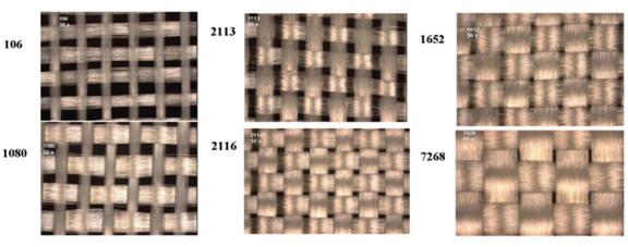
The fiberglass weaves are typically classified into different glass styles, based on the yarn count and the type of fiberglass yarn used, as listed in below table.
| Glass Style | Count Warp | Count per Inch | Warp Yarn | Yarn Fill | Glass Thickness |
|---|---|---|---|---|---|
| 106 | 56 | 56 | ECD-900 1/0 | ECD-900 1/0 | 0.0015 |
| 1080 | 60 | 47 | ECD-450 1/0 | ECD-450 1/0 | 0.0025 |
| 1280 | 60 | 60 | ECD-450 1/0 | ECD-450 1/0 | 0.0022 |
| 2113 | 60 | 56 | ECE-225 1/0 | ECD-450 1/0 | 0.0029 |
| 2116 | 60 | 58 | ECE-225 1/0 | ECE-225 1/0 | 0.0038 |
| 3070 | 70 | 70 | ECDE-300 1/0 | ECDE-300 1/0 | 0.0034 |
| 1652 | 52 | 52 | ECG-150 1/0 | ECG-150 1/0 | 0.0045 |
| 7628 | 44 | 31 | ECG-75 1/0 | ECG-75 1/0 | 0.0068 |
The tighter the weave netting, the more uniform the dielectric constant. Loose weaves resulting in less uniform dielectric constants in the PCB laminate can cause trace impedance variations and propagation skews in tightly matched signals, such as differential pairs that directly reference the weave. For example, on a sparse weaving such as glass style 106, one leg of the differential pair may be routed directly over a fiber weave while the other leg is routed between the fiber weaves. This results in a different εr for each leg of the differential channel.
In general, to counteract this skew, route traces at a small angle in a zig-zag fashion relative to the fiberglass strands to average out the number of on-weave and off-weave traces. This technique requires more board routing room and may not be achievable in a space-constrained board. In this situation, select a more tightly woven glass style for the dielectric surrounding the high speed trace layers. Because more tightly woven glass styles add cost to the PCB, a good compromise is to select a medium woven glass style such as 2116 for the high-speed trace layers and a lower-cost 106 or 1080 glass style for other lower-speed signal layers.
For board design with ultra-high speed transceiver signals, Intel® recommends to choose spread glass materials to mitigate this effect.