Visible to Intel only — GUID: dmi1461675640527
Ixiasoft
2.1. Installing and Licensing Intel® FPGA IP Cores
2.2. IP Catalog and Parameter Editor
2.3. Specifying the IP Core Parameters and Options ( Intel® Quartus® Prime Pro Edition)
2.4. Simulating Intel® FPGA IP Cores
2.5. Simulating the FIR II IP Core Testbench in MATLAB
2.6. DSP Builder for Intel® FPGAs Design Flow
4.1. FIR II IP Core Interpolation Filters
4.2. FIR Decimation Filters
4.3. FIR II IP Core Time-Division Multiplexing
4.4. FIR II IP Core Multichannel Operation
4.5. FIR II IP Core Multiple Coefficient Banks
4.6. FIR II IP Core Coefficient Reloading
4.7. Reconfigurable FIR Filters
4.8. FIR II IP Core Interfaces and Signals
Visible to Intel only — GUID: dmi1461675640527
Ixiasoft
4.1. FIR II IP Core Interpolation Filters
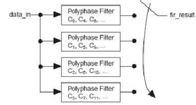
An interpolation filter increases the output sample rate by a factor of I through the insertion of I-1 zeros between input samples (zero padding). Polyphase decomposition reduces the number of operations per clock cycle by ignoring the zeros padded in between the original input samples. Polyphase interpolation filters provide both speed and area optimization because each polyphase filter runs at the input data rate for maximum throughput.
Figure 9. Polyphase Interpolation Block Diagram
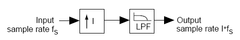
Figure 10. Polyphase Decomposition for Interpolation Filters
The FIR II IP core implements interpolation filters using a single engine that the different phases timeshare to optimize area. This implementation changes the overall throughput of the filter and the input sample rate. The throughput of the filter is the rate at which the filter generates the output (one output every K clock cycles). The input sample rate is the rate at which the filter processes input data samples (the input needs to be held for L clock cycles).
The values of K and L for the throughput and input sample rate of FIR II interpolation filters depend on the filter architecture.
| Architecture | Equations |
|---|---|
| Fully serial | K = N L = N I |
| Multibit serial | K = N/M L = N I / M |
| Fully parallel | K = 1 L = I |
| Multicycle | K = C L = C I |
For systems that require higher throughput and input data rate, Intel recommends that you use parallel or multicycle variable structures.