4.15. Intel® Stratix® 10 EPE - Intel® Enpirion® Worksheet
Each row in the Regulator Selection table of the Intel® Enpirion® worksheet of the Early Power Estimator for Intel® Stratix® 10 devices represents the power solution for a single regulator group.
Intel® Enpirion® power devices are available that satisfy the power requirements for the power rails on FPGA devices. Power devices are selected based on load current, input and output voltages, and power-delivery configuration.
Regulator groups are created by combining rails that can be allowably supplied from the same source. Intel® Enpirion® device selection is enabled when Power Characteristics in the Main worksheet is set to Maximum, and the Regulator Group section of the Report worksheet is set up correctly with no grouping errors.
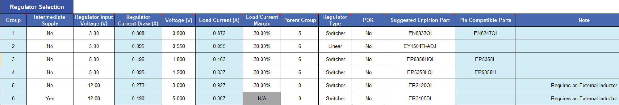
In the following figure, a 12-V off-line regulator supplies input power for Groups 5 and 6. The regulator for Group 6 is an intermediate supply, which does not directly power any of the FPGA supplies, but provides input power to regulators for Groups 2, 3, and 4. The 3-V regulator supplying Group 5 provides power for FPGA supplies, but also acts as an intermediate supply providing input power for Group 1.
Figure 23. Intel® Enpirion® Worksheet of the EPE Spreadsheet for Intel® Stratix® 10 Devices
| Column Heading | Description |
|---|---|
| Group | The regulator group number for this regulator. The regulator group numbers correspond to the group numbers shown in the Report worksheet. |
| Intermediate Supply | Indicate whether the supply is an intermediate supply. An intermediate supply is driven by a regulator that is not connected to any supply rails on the FPGA. Instead, such a regulator drives other regulators. If a regulator provides power to both the FPGA and other regulators, this field should be set to No. |
| Regulator Input Voltage (V) | Specifies the input voltage for the regulator. The input voltage must be higher than the output voltage. If this regulator has a parent, its input voltage is automatically set to the parent's output voltage. |
| Regulator Current Draw (A) | Specifies the required input current to the regulator. It is assumed that all regulators have a current efficiency of 85%. |
| Voltage (V) | Specifies the output voltage of the regulator. The voltage equals the voltage of the supply rail connected to this regulator. |
| Load Current (A) | Specifies the load current required by the pins from the regulator. This current equals the sum of all the supply currents that are connected to this regulator, multiplied by (1 + Load Current Margin). In addition, if this regulator is a parent of other regulators, the Load Current also includes the sum of all the children's input currents. |
| Load Current Margin | Margin added to the load current to account for component variability. |
| Parent Group | The group number of the regulator that supplies input voltage to the regulator in the current row. This value is applicable only when the input voltage is provided by another regulator on this worksheet. |
| Regulator Type | Choose the type of the regulator. |
| POK | Select Yes to select a regulator with a Power OK (POK) output to assist with sequencing. |
| Suggested Enpirion Part | Specifies suggested Intel® Enpirion® parts to implement regulator for a given row, which meet the voltage and current requirements for this row. To finalize regulator selection, evaluate VRM voltage ripple specification and efficiency against the FPGA device requirement from the appropriate data sheets. |
| Pin Compatible Parts | Pin compatible parts are devices with equivalent or higher current capabilities that can be placed on the same PCB footprint as the suggested Intel® Enpirion® part. Additional components or changes to component values may be required when using a pin compatible part. |
| Note | A note may be displayed here, depending on the value chosen under Suggested Enpirion Part. |