Visible to Intel only — GUID: mba1628537157921
Ixiasoft
1. Power Distribution Network
2. Gigahertz Channel Design Considerations
3. PCB and Stack-Up Design Considerations
4. Device Pin-Map, Checklists, and Connection Guidelines
5. General Board Design Considerations/Guidelines
6. Memory Interfacing Guidelines
7. Power Dissipation and Thermal Management
8. Tools, Models, and Libraries
9. Reference Designs and Development Kits
10. Document Revision History for AN 958: Board Design Guidelines
4.1. High Speed Board Design Advisor
4.2. Complete Pin Connection Table by Device
4.3. Pin Connection Guidelines By Device
4.4. Design for Debug with JTAG Pins
4.5. Hot Socketing, POR and Power Sequencing Support
4.6. Implementing OCT
4.7. Unused I/O Pins Guidelines
4.8. Device Breakout Guidelines
4.9. Additional Resources
5.1.1. Material Selection and Loss
5.1.2. Cross Talk Minimization
5.1.3. Power Filtering/Distribution
5.1.4. Unused I/O Pins
5.1.5. Signal Trace Routing
5.1.6. Ground Bounce
5.1.7. Understanding Transmission Lines
5.1.8. Impedance Calculation
5.1.9. Coplanar Wave Guides
5.1.10. Simultaneous Switching Noise Guidelines
Visible to Intel only — GUID: mba1628537157921
Ixiasoft
1.4. Plane Capacitance
For high frequencies, decoupling using discrete capacitors is less effective. Use power plane capacitance for decoupling noise at these frequencies. You can understand the concept of plane capacitance by studying the classic parallel plate capacitor, as shown in Figure 1.
Figure 1. Parallel Plane Capacitance
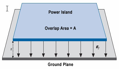
An electric field is created when there is a power plane next to a ground plane. The upper area in Figure 1 shows the power island or plane, the lower area shows the ground plane, and the arrows represent the electric field lines. This electric field gives rise to a capacitance, the magnitude of which is shown by the following equation:
C=(εοεrA)/h
Where
- εο = permittivity of free space
- εr = relative permittivity of the dielectric used
- A = area of overlap
- h = separation of the planes.
If there are ground planes on both sides of the power island, then the capacitance needs to be calculated for each side and added to determine the total capacitance.
Plane capacitance is the primary way of decoupling at high frequencies, so it must be an integral part of any high-speed design. At high frequencies, the discrete capacitors are not very effective.
As an example, consider the following.
Example: Determine the parallel plate capacitance for 1 square inch of area overlap in an FR-4 dielectric (εr = 4.5) and a separation of 4 mils.
Solution:
Applying these numbers to the capacitance equation above yields C = 253 pF. Therefore, there is about 253 pF per square inch of area overlap on a typical FR-4 board with 4 mils of separation. The value scales inverse linearly with separation and linearly with area.